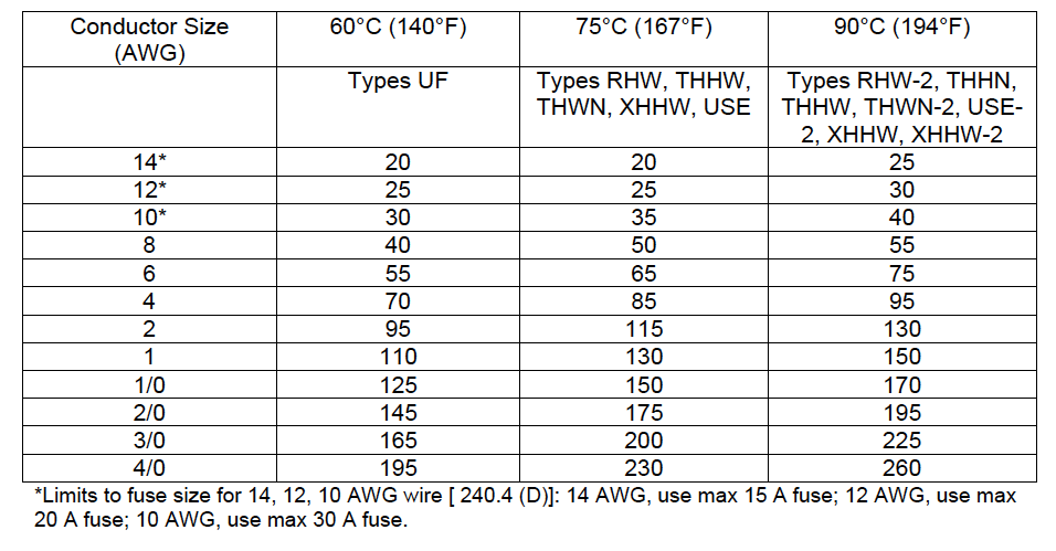
STANDARDS & APPROVALS: Welders should look for key industry standards and approvals, ensuring quality and performance while protecting against substandard manufacturing. Superior flexibility, durability, and resistance properties are also vital to a welding cable’s ability to perform in a range of demanding applications and environments. An improper gauge size will not carry the anticipated current, which can cause excessive heat absorption (melting and fire hazard), failure, and damage to equipment.ĬONSTRUCTION: Welding cable construction uses a multi-stranded single conductor insulated (or jacketed) by a single layer of EPDM or neoprene thermoset with a temperature rating of -50☌ (-58☏) to 105☌ (221☏). If a longer cable is needed, the user should consider thicker gauge sizes. A longer, thinner welding cable will carry lower ampacity. GAUGE SIZE: It is critical to select the proper gauge size for the given welding application. It is essential to keep in mind (1) ampacity ratings decrease as length increases due to additional resistance, and (2) welding cable should be spread apart to allow heat to dissipate during use. LENGTH: Welding cables should be long enough to provide the user with adequate length to reach all work areas-without becoming a hazard. Specifications that should be considered when selecting welding cable include:ĪMPACITY: Welding cable ampacity (also known as current-carrying capacity or current rating) refers to the maximum amount of current (in amperes) that a cable conductor can continuously and safely carry without exceeding the operating temperature rating. This information is for reference only, and it is highly recommended the user consult a licensed electrical engineer for a particular welding application.įor welding applications, using the proper cable gauge size is critical to ensure high-quality welds and protect the user and their welding equipment. These resistance values are valid only at 75☌ (167☏) and for the parameters as given, but are representative for 600-volt wire types operating at 60 Hz.Direct Wire’s welding cable ampacity chart intends to support and guide welding professionals toward the proper cable gauge and length. Capacitive reactance is ignored, since it is negligible at these voltages. Wire conductivities are 100 percent IACS copper and 61 percent IACS aluminum, and aluminum conduit is 45 percent IACS. These values are based on the following constants: UL-Type RHH wires with Class B stranding, in cradled configuration. Table 9 Alternating-Current Resistance and Reactance for 600-Volt Cables, 3-Phase, 60 Hz, 75☌ (167☏) - Three Single Conductors in Conduit R, Aluminum: Alternating-Current Resistance for Aluminum Wires NEC Table 9 Wire Size R, Copper: Alternating-Current Resistance for Uncoated Copper Wires

Table nomenclature (adjusted slight from the NEC to improve readability online): That said, Table 9 is useful for real-world calculations. If the operating conditions deviate from these assumptions, the values need to be corrected. Pay close attention to the notes at the bottom of the table. These values are particularly useful for performing voltage drop calculations when the power factor is known. Units of resistance and reactance are ohms per 1,000 feet.
#Nec wire size chart code
Table 9 in the National Electrical Code is provides copper and aluminum conductor resistance and reactance data.


 0 kommentar(er)
